
Hi ALL,
Hope someone can offer advice, I have devoured a lot of information from this site in regards to suitable camshafts for my VCH.
Included in this was some useful dissertations from David Anderson and an excellent article from Paul Jameson. The quandary I have is the effects thereof and at what point the numbers are derived and if there is a difference in measuring at the pushrods with a twin lobe cam as opposed to the single lobe cam. David's' numbers are at 0.050" lift with I suspect a single lobe camshaft and some I found in Harley are at 0.25" the others are not usually stated, there is also a question if ramps are used or not and the difference between 1" and 1.5" base circles.
The reason for these questions are that after assembly of the my engine (9:1 comp and 97 octane petrol) I have had no end of issues getting it started . (after a knee replacement it's great exercise kick starting a 500 single) and getting a smooth running engine. First the carby was suspected and I changed from a 1 1/16" 376 monobloc to a 1 1/8" 389 monobloc. both carbs had float levels set with a clear float bowl cover and pilot jets were properly cleaned. Starting was still very temperamental I then changed back to the original 1 7/32" T10Gp1 as the smaller carbys, "O" rings at the flanges were close to the inlet of the head diameter and it may have been sucking air. The GP with the correct flange ran a little better but valve clearances seemed to be very critical (increasing clearances improved things so I suspected valve timing).
After checking the valve timing the numbers seemed way out from all recorded values when the timing marks on camshaft and 1/2 time pinion aligned correctly.
After advancing the cam one tooth the numbers at 0.025" lift were 37 72 62 45 which appear to be the same as the reported values for the HS Mark III cam from Paul's notes. I think the cam I am using was given to me by Kel Carruthers' father Jack and was one of his or Claude Cartledge's grinds and I had completely forgotten about the one tooth advance until now so had not checked it on assembly.'
So questions are:
1) When supplied with valve timing values what should be the default measurement heights to check them at ?
2) Can they be taken at say 0.005" then a factor be applied to reflect other values assuming the contour of the cam is symmetrical ?
3) Will the total lift above base circle effect the lift that should be used for the timing measurement ?
4) Crystal Ball stuff .. would the above cam i have mentioned be ok to use... (there may also be some material removed off the followers so that is a mystery David's diagram he posted in PDF format appears to be corrupted so I can't check that).
Sorry for such a long post but hopefully answers may help others in the future,
Brian
Another cam question
-
Brian_Walker
- Holder of a Nylon Anorak

- Posts: 173
- Joined: Mon Mar 19, 2018 9:40 am
- Location: Sydney, Australia
- Contact:
Another cam question
1951-52 VCH under restoration
-
david.anderson
- Holder of a Golden Anorak

- Posts: 1532
- Joined: Mon Mar 28, 2011 4:52 am
- Location: south coast NSW Australia
- Contact:
Re: Another cam question
Brian
I have a lot of hot cams for Ariel singles. The only way to compare valve timing on paper is to measure the valve timing at the same lift (or tappet clearance) and because various cams have short or long ramps then the figure of .050” is currently the generally accepted lift figure in the industry as it will be clear of the influence of any ramps. The cam that I have with the longest ramp is the Claude Cartledge cam and to measure it at a low lift figure makes it appear much hotter than it is.
I have both single lobe and twin lobe cams in various states of tune.
Ariel quote the valve timing for the single lobe cam at .023” inlet and .025 exhaust (figure that one out) while the twin lobe Ariel cam is quoted at .010”. Those are of course clearances for checking the valve timing but are not the running clearances. So if you are going to check for a possible original Ariel grind then you should use the figures above. There is no factor that can be applied to give a timing at x lift if the initial figure is taken at .005” lift.
The Ariel valve actuation is not symmetrical. Even if the cam itself is symmetrical, it is the action of the lever type followers that introduces an asymmetrical action. Because of the cam lever effect, it is possible to make the twin lobe cam asymmetrical, but to have a symmetrical valve action, as there is one lobe for each valve, however that is not possible on the single lobe cam due to the leading and trailing lever followers. When cam levers are ground to a flatter radius, the asymmetric action becomes more accentuated.
It was typical of Claude Cartledge to grind a cam that needed to be advanced by one tooth (abt 15 degrees) and my own Cartledge cam needs to be advanced by a tooth. However I am not aware that Cartledge did any grinds on the single lobe cam. In his discussions with me he inferred the single lobe cam was not the cam for a performance grind (wrong). Most of Cartledge’s grinds were after stellite welding the cam so is your cam stellite welded.
It is unlikley that your cam is a genuine mk3 cam as you would not need to advance a genuine mk3 cam by one tooth. As for the correct running tappet clearance you would need to carefully measure the ramps on the cam. If the ramp lift is about .010” over 50 degrees of engine rotation then a running clearance of about .010 may be appropriate, as is the case with the original HS cams.
From the valve timing that you have quoted the cam you have appears suitable for road use. It is certainly not as hot as the 1956 mk1 cam. It has a similar valve timing to the 1954 mk1 cam.
David
-
Brian_Walker
- Holder of a Nylon Anorak
- Posts: 173
- Joined: Mon Mar 19, 2018 9:40 am
- Location: Sydney, Australia
- Contact:
Re: Another cam question
Thanks David, my cams are all twin lobe cams I just mentioned that the MKIII mentioned in Paul's article gave similar numbers to my twin lobe and I thought it may have been measured at 0.025".
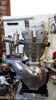
The cam I mentioned is 25 55 50 32 at 0.050" the lift is 0.330 but the profile of the followers looks like it has been flattened, the cams have built up from A7/642 cams and have been built up a you mentioned. Here is the cam I'm using..
The cam I mentioned is 25 55 50 32 at 0.050" the lift is 0.330 but the profile of the followers looks like it has been flattened, the cams have built up from A7/642 cams and have been built up a you mentioned. Here is the cam I'm using..
- cam2.jpg (33.02 KiB) Viewed 2028 times
1951-52 VCH under restoration
-
david.anderson
- Holder of a Golden Anorak
- Posts: 1532
- Joined: Mon Mar 28, 2011 4:52 am
- Location: south coast NSW Australia
- Contact:
Re: Another cam question
Brian
The valve timing does not replicate any cam that I have. The stellite weld appears to be neat with no overflow between the lobes. As such I doubt that Cartledge did the welding as my Cartledge cam weld is not that neat.
My Corish cam has a timing of 23 55 64 14 at .050” lift. I know that Corish experimented with altering lobe centres and came up with what he believed was the ideal inlet and exhaust centre lines. I have a master that Corish ground from and it is easy to alter lobe centres on the master. Lobe centres on my cam are 110.5 degrees apart which is fairly wide for the track whereas your cam lobe centres are 102 degrees separation which is more what would be expected for the track. However my Corish cam only lifts .313” inlet and .307 exhaust at the valve. Is the lift figure that you quoted measure at the valve or direct from the cam.
David
-
Brian_Walker
- Holder of a Nylon Anorak
- Posts: 173
- Joined: Mon Mar 19, 2018 9:40 am
- Location: Sydney, Australia
- Contact:
Re: Another cam question
HI David, took the measurements off the pushrods...
Hope this method is OK as with engine in frame hard to get lift from valve cap.
The followers look to be about 5/8" but flattened a bit ( next to 5/8" copper washer for example"
Hope this method is OK as with engine in frame hard to get lift from valve cap.
1951-52 VCH under restoration
-
Brian_Walker
- Holder of a Nylon Anorak
- Posts: 173
- Joined: Mon Mar 19, 2018 9:40 am
- Location: Sydney, Australia
- Contact:
Re: Another cam question
HI David, I took my measurements off the pushrods...
Hope this method is OK as with engine in frame hard to get lift from valve cap.
The followers look to be about 5/8" but flattened a bit ( next to 5/8" copper washer for example"
I found an old post of yours with 0.010 values for various cams including a very old one of Claude's, you commented that it had a poor idle and spitback ... mine has exactly the same numbers.
Here is an extract from your original post..
"Ted Carey cam 35btdc 85abdc 82bbdc 60atdc measured at .010 clearance run with 5/8 radius followers .390 lift exhaust.400 lift inlet
Vic Lyons cam 45btdc 70abdc 90bbdc 70atdc measured at .010 clearance run with 5/8 radius followers
Claude Cartledge cam 45 btdc 95abdc 85bbdc 75atdc measured at .010 clearance run with std followers. I measured the valve timing for this cam many years ago and may not have been as accurate as I now am.
(My measurements were within 1 degree of each of your measurements so one of us must be doing things right.)
All cams are twin lobe and have been built up with stellite weld. The neatest weld is on the Lyons cam.
the Lyons cam and the Cartledge cams are currently in my 57VHs and I don't have any photos.
The Carey and Cartledge cams have a similar appearance. I have posted photos of the Carey Cam
The Lyons cam has straighter sides and a flat top (matchbox type) the Lyons cam however idles so slow I cannot believe it and has good power throughout the rev range. The Carey Cam idles slow and well and has good power throughout.The Cartledge cam will idle ok but nothing like as slow. Not much down low but heaps of power up high. The spitback out the carb when revved from down low is considerable."
Mine has 343 inlet lift and 337 ex (from pushrod) a little less that yours but that maybe due to how I measured the it. Some suggest the total cam height - base circle.
Little wonder the carb settings were getting me worked up also running on Unleaded 95 is probably a little different than Shell A and kick starting is not as easy as bump starting. (The gearbox now sports a kick starter)
Thanks for the feedback David very much appreciated.
1951-52 VCH under restoration
-
david.anderson
- Holder of a Golden Anorak
- Posts: 1532
- Joined: Mon Mar 28, 2011 4:52 am
- Location: south coast NSW Australia
- Contact:
Re: Another cam question
Brian
The welding near the edges of that cam looks too neat for Cartledge. Also Cartledge did not manage to grind all cams the same. He had several Ariel master cams and could vary the grind on the copy as he proceeded, which he often did if the weld was lacking in an area. A friend took a Triumph cam to him to be copied, and the copy was nothing like the original.
The rockers are 1 – 1 ratio so lift should be the same.
Do you know what happened to Cartledge. When I knew him he was living at 13 Athelstane Ave in Arncliffe. His workshop was at the rear of his house and his son was working for him. I know he was retiring and his son was to take over the business, but both then seemed to disappear. I know he was into stamp collecting, and he had several houses on the south coast at Burrill Lake Bawley Point and Pebbley Beach and Durras Lake. About 20 years ago I checked Council ownership records for those areas and no properties were owned by him in those areas.
David
Who is online
Users browsing this forum: No registered users and 11 guests