
More dynamo issues.
-
alan.moore
- Holder of a Golden Anorak

- Posts: 1457
- Joined: Sat Jul 19, 2014 1:29 pm
- Location: Leicestershire UK
- Contact:
Re: More dynamo issues.
Bill, how do you check this resister i.w where are the wires at each end?
1939 VH Redhunter;1942 RN WNG;1951 Triumph 6T Thunderbird;1970 BSA B175 Bantam;1986 Yamaha SRX600 single;1952 VHA engined project
http://cloggymoore.wix.com/triumph-pre-unit-6t
http://cloggymoore.wix.com/triumph-pre-unit-6t
-
Phil B

- Holder of a Nylon Anorak

- Posts: 208
- Joined: Sun Apr 23, 2017 5:26 pm
- Location: Beverley, Yorkshire
- Contact:
Re: More dynamo issues.
Sorry for not updating, currently on a snap break up in the North Pennines. Normal service resumes on Saturday. Itching to get on with it!!
NON SUFFICIT ORBIS
1939 NH
1939 NH
-
bill.bottrill
- Posts: 64
- Joined: Wed Nov 04, 2015 7:36 pm
- Contact:
Re: More dynamo issues.
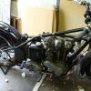
This photo shows you the resistor,sorry I can't put arrows on etc.
Can you see it's the round black jobby,to check it you need the fade plug out.one meter probe on the frame (ie V) and the other meter probe on the copper clip or the flat strip attached to it.can you see the points or contacts worked from the coil in the forground you need to put a sheet of paper between them or you won't get a reading
I would advise you disconnect the battery earth if you are poking around on the bike as even though it's a small battery a short can fry the wiring!
Perhaps we can demystify a bit of this control box,everybody knows to join F to D on the dynamo to check if it's charging, but look, that's all that is happening inside this bit of the mcr2
The F and D wires come straight from the dynamo to the control box plug (F) a(D) e. you can see (F) (bottom rh side) on the photo and the bit of soldered wire that curls around to an insulated screw on the back of the frame(V) this screw holds one of the contacts of the points on the other side of the frame(V) all insulated from the frame(V)
The other half of the contacts is attached to the movable arm of the coil which in turn is attached to the frame (V) through a bendy flat spring,the two screws on top of the frame (almost there!) the frame(V) is directly attached to (D)
So at rest the contacts are closed so it's just doing the same as joining (F)to(D)
Also the resistor can now be seen to be straddling the contacts from the insulated screw along the flat wire through the resistor and down to the frame (V) the frame is on an insulated panel so it doesn't short to the fixing bolts etc.
-
bill.bottrill
- Posts: 64
- Joined: Wed Nov 04, 2015 7:36 pm
- Contact:
Re: More dynamo issues.
Sorry I've hi-jacked your thread, I should have put the above and the previous post under keith's dynamo problem bill
-
Phil B
- Holder of a Nylon Anorak
- Posts: 208
- Joined: Sun Apr 23, 2017 5:26 pm
- Location: Beverley, Yorkshire
- Contact:
Re: More dynamo issues.
Absolutely no problem Bill. All info is useful and now you’ve posted, people can search for your posts.
NON SUFFICIT ORBIS
1939 NH
1939 NH
-
nevhunter
- Holder of a Platinum Anorak

- Posts: 5053
- Joined: Tue May 10, 2011 9:42 am
- Location: Victoria.. Australia.
- Contact:
Re: More dynamo issues.
Joining F to D won't apply any power to provide the initial magnetism.. The cutout points are apart. If you close them manually sometimes they arc together F to D will eliminate the cutout-regulator when testing the generator by itself. Don't run it at high revs as the voltage can go quite high. Nev
Who is online
Users browsing this forum: No registered users and 1 guest