
square four valve timing
square four valve timing
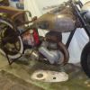
I haven't put the head back on my mk1 sq 4 yet , still on with valve guides , but tonight I was looking at the valve timing and fitted the chain etc using a dti on the push rods . First time it was way out on the degree wheel although I had followed the fitting instructions in the manual I have . It then dawned on me that as the cam shaft goes around twice to the cranks once that i could be 180 degrees out . I pulled it back off and refitted it with the crank on a different stroke i.e. one revolution on and it now seems to be right . No 1 inlet valve opening 25 degrees before tdc . Does this sound right and is it correct that i could in fact time it up 180 degrees out .
51 mk1 Areil Square Four
55 DB 500 BSA Gold Star
55 Matchless G9
67 BSA B44
06 Ducati 999R
55 DB 500 BSA Gold Star
55 Matchless G9
67 BSA B44
06 Ducati 999R
Re: square four valve timing
Wish I had checked the valve timing on piston no. 3 before id re done it that would have answered my question .
51 mk1 Areil Square Four
55 DB 500 BSA Gold Star
55 Matchless G9
67 BSA B44
06 Ducati 999R
55 DB 500 BSA Gold Star
55 Matchless G9
67 BSA B44
06 Ducati 999R
-
Bob.Murphy

- Holder of a Golden Anorak

- Posts: 1137
- Joined: Thu Nov 29, 2012 10:32 pm
- Location: Kirkliston, on the West side of Edinburgh.
- Contact:
Re: square four valve timing
Errr NO - the Camshaft turns at HALF engine speed (engine goes around twice for the camshaft's once). There are twice as many teeth on the camshaft sprocket as there are on the engine sprocket.GuyWalton wrote: It then dawned on me that as the cam shaft goes around twice to the cranks once that I could be 180 degrees out .
You can still be 180 degrees out - or any other factor - if you don't get the timing right
Its a LONG time since I timed a Square Four, but aren't there marks on the cam sprocket and engine sprocket that must be aligned (with the sprockets keyed to their shafts) ??
Someone with recent experience will be along shortly
Bob.
My avatar shows the late Len Rich in 1970 with the bike I now have - a 1958 Ariel VH
Re: square four valve timing
yes course it does my mind was fried trying to time it . I did have the timing marks lined up. Two holes on the camshaft pointing to the back crank shaft and back crankshaft line pointing to the camshaft with the keyway at the bottom but somehow I was way out on the degree wheel . Anyway I took them off and started again after turning the engine over once and it all seems good now . Think it is probably better that I wait till the head is back on before I try to get it timed better with the degree wheel .
51 mk1 Areil Square Four
55 DB 500 BSA Gold Star
55 Matchless G9
67 BSA B44
06 Ducati 999R
55 DB 500 BSA Gold Star
55 Matchless G9
67 BSA B44
06 Ducati 999R
-
keith wainwright
- Holder of a Nylon Anorak

- Posts: 236
- Joined: Tue May 08, 2012 2:26 pm
- Location: Surrey
- Contact:
Re: square four valve timing
Hi Guy this will help you once the valve gear has been assembled.
Mk1 and Mk11 Ariel Square Four Valve timing.
Tools required.
1 Feeler gauges imperial 0.006” and 0.008”
2 Dial gauge. (Magnetic base would be good)
3 1/8 Witworth small ring spanner and open ended spanner. (Locknut on tappet adjusting screw)
4 6 BA open ended spanner. (square on tappet adjusting screw)
5 5/16” x 3/4” long BSF bolt and washer.
6 5/8” BSW socket + long bar for the socket. (Crankshaft and camshaft sprockets)
Please do not use hammer and chisel. (It hurts)
7 7/16” BSW socket or ring spanner for Dynamo sprocket.
8 Timing Disk. (Purchased an aluminium backed disk from E bay £12.00)
9 Stiff wire to fabricate TDC marker for timing disk.
10 14mm TDC timing calibration tool. (About £12.00 on E bay)
11 Packet of Hob Knobs or similar together with some tea bags.
Short cut terms used.
AOMC= Ariel Owners Motorcycle Club.
TDC = Top Dead Centre.
BDC = Bottom dead centre
BTDC = Before Top Dead Centre.
ATDC = After Top Dead Centre.
BBDC = Before Bottom Dead Centre.
ABDC = After Bottom Dead Centre.
IV = Inlet Valve.
EV = Exhaust Valve.
BSW= Whitworth spanners and sockets.
BSF= British Standard Fine.
Engine assembled together with valve gear.
Valve timing using original timing marks on crankshaft and camshaft sprockets.
Rotate 5/8” BSW nut on front Right Hand crankshaft,t until the back crankshaft sprocket keyway is at BDC.
This will bring the datum mark on crankshaft sprocket in line for timing to the camshaft holes.
Fit timing chain, slipping over dynamo sprocket and positioning over camshaft and crankshaft sprockets, so that the datum mark on crankshaft sprocket is in line with the two holes in camshaft sprocket. You may need to do this several times to achieve the correct settings.
Both camshaft and crankshaft sprockets will need to be off the shafts but can be both slipped back onto their relevant shafts Ok with chain attached.
Fit chain tensioner spring Mk1 or on Mk11 chain tensioner bracket and adjust to approximately ¼” up and down movement on chain.
Leave the camshaft and crankshaft sprocket nuts, nipped up loos at this stage.
To position TDC accurately, screw in TDC calibration tool into plug hole No 1 cylinder (Right hand side front cylinder) position dial gauge on top of TDC tool. Slowly rotate engine in an anticlockwise direction on the 5/8” BSW nut on the right hand front crankshaft. (Timing cover side)
Until you hit the high spot on the dial gauge, this will be TDC.
Check that the 5/16” BSF thread is clear on the end of the crankshaft, by screwing in 5/16” BSF bolt.
Note: Some of the early crankshafts did not have this 5/16 BSF threaded hole.
May need to be cleared with a 5/16” BSF tap. These threads often become damaged.
Tighten up the 5/16 BSF bolt into the end of the crankshaft, securing the timing gauge at TDC.
Fix stiff wire and bend to make a pointer at TDC on the timing disk.
The crankshaft datum mark and holes in camshaft should line up with the centre line of crankshaft and camshaft.
Put the kettle on and make a cup of tea together with a couple of chocolate biscuits for achieving this so far.
Set the valve clearances on number 1 cylinder 0.000 inlet 0.000 exhaust.
Make up a chart as below.
IV BTDC Open Manufactures Settings. 25
IV ABDC Close “ “ 55
EV BBDC Open “ “ 60
EV ATDC Close “ “ 20
Set dial gauge up on top of inlet valve tappet, pre load the dial gauge and set to 0. Very slowly rotate engine in an anticlockwise direction on the 5/8” BSW nut on front right hand crankshaft.
Until a reading moves the dial gauge slightly from zero, this is the valve starting to open.
Take a reading from the timing disk.
Carry on rotating engine anticlockwise until the dial gauge returns to zero. (This last stage of the valve closing needs the engine to be indexed in very small increments) The longer the socket bar on the 5/8” BSW socket the, better accuracy will be achieved.
Note the reading on the timing disk and record above.
Carry out the same procedure on the exhaust valve and record the readings from timing disk on the above chart.
Carry out the above check several times to achieve the average readings.
Engine set at TDC on No 1 cylinder and crankshaft keyway at BDC, you will note that the crankshaft sprocket datum mark will be in line with the two holes in the camshaft sprocket.
Note that the key way on rear crankshaft sprocket will be at BDC, you will also note two extra keyways on crank shaft sprocket.
Positioned to the left of TDC this key gives 5.55 advance on Simplex. 3.0 retard on Duplex.
Positioned to the right of TDC this key gives 5.55 retard on Simplex. 3.0 advance on Duplex.
One Tooth Simplex 25.7. One Tooth Duplex 20.
By using the above keyways and tooth settings you can achieve very closely original manufactures valve timings.
Remember worn sprockets, timing chain, camshaft and followers will give retarded readings and may be difficult to achieve the above settings.
If you experience difficulty adjusting valve timing to the above settings, AOMC have manufactured Duplex sprockets with 4 keyways enabling 5 deg steps throughout.
In my experience of building M1 and Mk11 engines, I have never been able to achieve the manufactures settings exactly. My rule of thought is, this is not a highly tuned performance engine and provided that you can get those figures as close as possible on the retarded side by approximately 6 deg this would be considered OK.
Well done if you have achieved the above successfully, you can put the kettle back on and make another cup of tea, this time with 3 chocolate biscuits as a reward.
New camshaft with quietening ramps. (Part Number 1960-53)
New camshaft tappet valve clearances Exhaust 0.008” Inlet 0.006”
-
brenton.roy
- Holder of a Golden Anorak
- Posts: 2056
- Joined: Sun Feb 27, 2011 1:13 pm
- Location: Adelaide, South Australia
- Contact:
Re: square four valve timing
That's very comprehensive Keith. Thank you.
'51,'56 Squares, '48 VH, '27 Model C, R67/2, Mk IV Le Mans, '06 Super Duke and Ariel projects.
Re: square four valve timing
Thanks for that ill print it off and follow it to the letter once i get the head on .
51 mk1 Areil Square Four
55 DB 500 BSA Gold Star
55 Matchless G9
67 BSA B44
06 Ducati 999R
55 DB 500 BSA Gold Star
55 Matchless G9
67 BSA B44
06 Ducati 999R
Who is online
Users browsing this forum: No registered users and 37 guests